MAREX MG
Turbo Fan Project
Subject: ISS Amateur Radio Turbo Fan Project
Date: September 19, 2007
From: Miles at MarexMG
I am working on several amateur radio project proposals for the International Space Station. At the preset time these are only proposals.
Thermal Issues on ISS:
The temperature inside the space station is between 72-74 F (24C) with a typical internal air-pressure of 14.3 psi. The shirtsleeve environment is nice and comfortable for humans, however it is not a conducive environment for electronics.
In space there is no convection cooling, hot air does not rise in space (see links before regarding cooling on ISS). The lack of convection cooling causes most electronics to run hotter. What this means for electronics, is that you need to design your electronics to compensate for the loss of convection cooling when you place the electronics inside the ISS. Even if your device, in this case an amateur radio transceiver, has a built in fan and some heat sink mass that may not be enough to keep the transceiver cool enough during normal operations in a zero gravity environment. Most electronics used on ISS were specifically designed to be used in this zero gravity environment; the Off-the-Shelf radios for the Amateur Radio projects were not modified to compensate for Zero Gravity.
Thermal Problems with the Amateur Radio station:
On ISS we are currently using a Kenwood TM-D700 transceiver
for all of our current Amateur Radio operations. This is the third Kenwood that
we have used for manned space station operations. On the Space Station Mir, we
used the Kenwood TM-V7A and the TM-733. Both of the Mir radios had good mounting
locations with plenty of available airflow access. In December 2003, the Radio
on ISS was installed inside a small table. Unfortunately, this location
restricted airflow to the transceiver. In September 2006 the radio was moved
outside of the table to a location next to green table where it is
would get better access to cabin airflow.
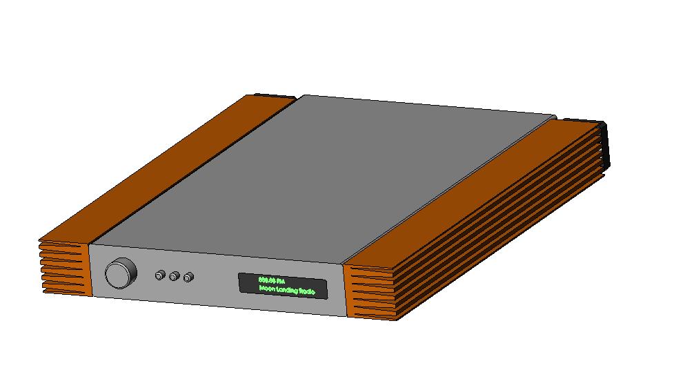
The Turbo Fan project:
The new Turbo Fan project proposal will add both Induction cooling and forced air cooling for a total of 15-CFM (15 cubic feet per minute or more than 1 cubic meter per minute). The initial plan calls for the fans to move air from the back of the radio towards the front of the radio. This movement will enhance the performance of the existing single Kenwood D700 fan, by drawing out the Hot air dissipated by the stock fan and expelling this hot air out of the bottom of the table area. The additional air movement will draw in more outside air and will also keep the radios power supply cooler.
The heat sinks will bolt onto existing screw terminals that are used for the mobile mounting bracket. Each heat sink will have a 1.6" square fan attached to the back of the heat sink.
Benefits:
The additional installation of the Turbo Fans will significantly improve the cooling of the D700 and increase its service life. The two fans will also help keep other ARISS hardware under the green table cooler by providing a larger volume of air flowing under the table.
The Turbo Fans will improve the ability of the TM-D700 to support higher duty cycle modes such as Cross Band Repeater and Slow Scan TV.
Support from the Amateur Radio community:
Marex needs your help. We are looking for a company that can donate their time and effort to the design and manufacture a few pairs of turbo fan heat sinks systems for the Kenwood TM-D700 transceiver. These heat sinks will then be tested with a TM-D700 to collect thermal performance data that can be used to support our theory and update our project proposal. ARISS keeps asking, "Can you prove it". With a few sets of custom heat sinks we can prove the theory and then move on to the next phase of the project. If the project is approved we could fly the upgrade kit to ISS.
Do you know of a company that can help?
If so, please contact Marex at wf1fgm@comcast.net
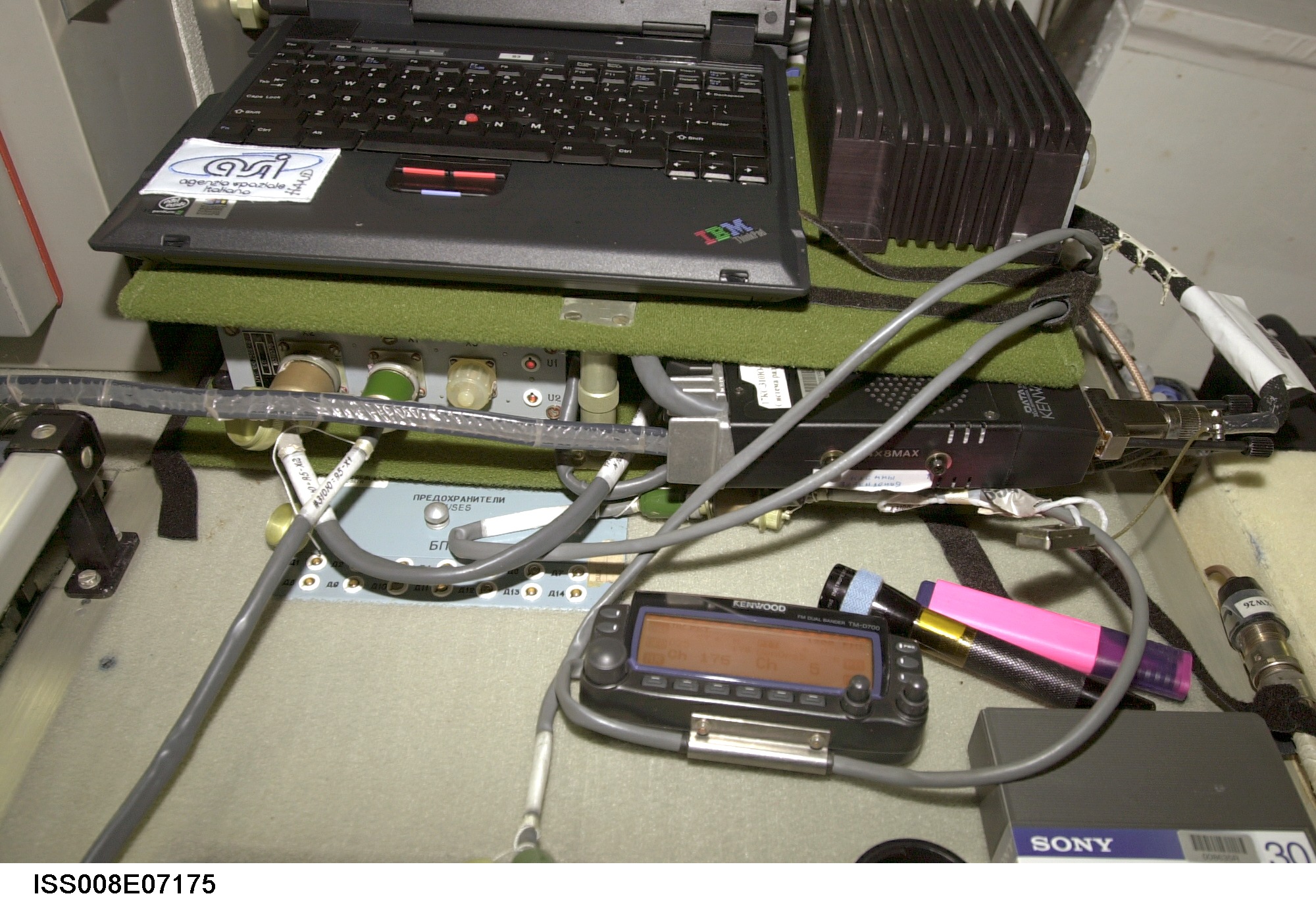
Pictures from ISS:
The D700 is the black box with the gray heat sink fins. It is in-between the two green table sections on the right hand side. The Gray box with the 3 connectors is the 28 to 12 VDC power converters. As you can see from this actual picture, the D700 heat sink is blocked from a steady source of cool air. There are two mounting screws visible on the side of the D700. There is where the new heat sink would be attached. The D700 was in this location for approximately 32 months. It was then moved out from under the table to just to the right side of the table in August 2006. The outside location may be a temporary location. There is a desire to stuff the radio back under the table. Extra space in the space station is in short supply.
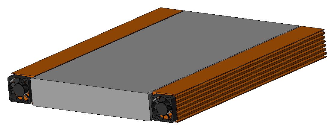
Details:
The two heat sinks will be custom cut from a single block of aluminum. There will be a Left and Right side heat sinks designed to match the sides of the D700. All edges will be polished smooth to prevent sharp edges
Fans:
The fans used on most small radios’ and PC are the same style 40x40x10mm. There may even be several of these types of fans already on ISS, including the one on the existing D700. The fans will receive their power from the external power jack on the D700 and will be controlled by the D700 power switch. When the radios turned on, the fans will be running. When the radio is turned off, the fans will be off.
Noise:
The noise generated by most of these types of fans is extremely small (29dB). In a normal office environment, you need to be really close to the fan, less than 1 meter to tell if the fan is running. Once installed in the Ham table, the crew would not be able to hear it at all in a quite office setting.
Size:
The Heat Sinks are being designed to be shorter than the D700 and the same height of the D700. The Heat sinks will make the D700 approximately 3.1 inches wider (80 mm). If space becomes a serious issue, we can attach only 1 turbo heat sink.
Specifications:
Voltage 12 vdc
Rotation speed 6500 rpm
Current 0.13A or 130mA at 12vdc
Rated Power 1.56 watts maximum
Air flow 7.7 CFM
Noise: 29dB
Bearing type: Sleeve
Size 1.57" x 1.57" x 0.39"
40 x 40 x 10 mm
Additional Pictures of the TM-700 installation on ISS
http://www.marexmg.org/hardware/kenwood.html
Power Specifications:
The D700 runs on 12 VDC and draws 500 ma while in receiving mode. When it is transmitting, the load will vary depending on the user selectable transmitter output values. (Note all values are approximate based on a 13.8 vdc source)
RF settings for the TM-700 on ISS.
Low 5 watts, 3 amps
Medium 10 watts, 4.5 amps
High 25 watts, approximately 8 amps
Note: The ISS version of the D700 has been modified not to exceed 25 watts of RF output. The Terrestrial version of the D700 has a high power setting of 50 watts.
The Space Station is pressurized to approximately 14 PSI, with a room temperature of between 72-74 F.
The D700 (on earth) typically runs at 88-90 F when sitting idle in receive only mode (with good ventilation). When transmitting at 45% duty cycle, the radio quickly heats up to 100-102 F (On earth with good ventilation).
After the heat sinks are installed, additional testing will be conducted to document the new thermal properties. From this data, we can better determine the recommended duty cycle loads for future projects.
Temperature Issues In space:
Here is some NASA background links on temperature control inside ISS.
Staying Cool on the ISS
http://science.nasa.gov/headlines/y2001/ast21mar_1.htm
Fan noise stories on ISS
http://www.spacedaily.com/news/iss-99o.html
Data from ISS:
At the present time we have no base line data for how hot this radio is operating in its current location. That information will be very valuable for current and future radio projects.
Radio Table:
The D700 transceiver is mounted inside the Amateur Radio table. This table is approximately 16 x 16 inches L x W, and it also has two tables separated by approximately 4 inches. All sides of the table are covered with an insulating type of green padding. The D700 transceiver is sandwiched in between the two table sections. This leaves 4 small side openings (16x4" approximate) for air ventilation. The backside opening is blocked by the ceiling. The three remaining side of the table appears to be open for some air movement. As a result of the small confined space, there is a very limited amount of air circulation under the table layers. The D700 also shares this confined space with the radios UN-fanned power supply.
You are visitor #
since August 2006